
Drawing from his two decades of residential engineering experience, M+K project manager Jason Bischoff, P.E., writes in the July/August 2024 issue of Journal of Light Construction about the pitfalls of leaving construction errors unchecked—illustrating how even minor errors can lead to costly and complex retrofits if not addressed promptly.
Avoiding Costly Structural Repairs
In my role as a project manager for a national structural engineering firm that specializes in residential design, I have the opportunity to learn about thousands of construction errors on a regular basis. Our firm has more than 65 engineers on staff working on projects across the U.S., and we are regularly tasked with providing quick turnaround retrofits to resolve construction errors to keep projects moving forward. From this well of experience, we’ve compiled a short list of the common construction errors with the most impactful retrofit requirements, along with some recommended preventative measures. Most of the situations described here can be avoided with oversight and awareness but are likely to balloon into major problems when overlooked. In most cases, the longer a construction error goes unaddressed, the more expensive it becomes to correct.
Out-of-Square Footings and Foundations
The need to keep footings and foundations square should be obvious, right? Still, nothing will stop a job quicker than finding out the foundation wall forms are overhanging the edge of the footing or the sill plates are overhanging the foundation walls. When these problems occur, it is worth pausing and reaching out to a design professional for direction on how to compensate. In some cases, the solution may be as simple as fastening a ledger to the side of the foundation to provide support for an overhanging sill plate. But in more drastic instances, more extensive or creative modifications to the foundations may be required. Depending on the scenario, it could be a much more difficult repair after the walls have been poured and even worse once the framing is installed.

Prevention: Measure twice, pour once. Make sure all measurements are checked prior to pouring. We recommend having an established process that clarifies whether the builder or the foundation contractor is accountable for verifying all dimensions prior to pouring the walls and footings and before any framing is set. Preferably, this is defined in writing in the subcontractor agreement.
Out-of-Level Foundations
A foundation that’s not level shouldn’t be much of an problem if it’s caught early. In an ideal situation, the framers install their sill plates as level as possible, shimming where necessary and checking level as subsequent levels are framed. It is imperative to check for level across all bearing points of a foundation. For example, if exterior wood-framed walls are bearing on a perimeter stem wall determined to be level, but the interior bearing walls are supported on a slab that is too high or too low, that is a recipe for major retrofits to those framed walls if not addressed early.
Prevention: Builders and their subcontractors need to ensure they are building from a level baseline, across all bearing points of the structure. A datum point should be established at one of the structural bearing points, and a laser or builder’s level should be used to verify that the rest of the structural bearing points are at the same elevation as the datum point.
Incorrect Steel Pipe Columns
Not all pipe columns are created equal (in the literal sense). For typical adjustable steel pipe columns, each manufacturer has its own rated load-carrying capacity. Many manufacturers require screw jacks to be embedded in the concrete, while others may have varying capacities for when the screw jack is not embedded. All column capacities will vary with the height of the column—so the column will have less capacity in a 9-foot basement versus an 8-foot basement. A good set of structural plans will provide thorough column specifications or provide column design loads to enable the correct column to be selected.
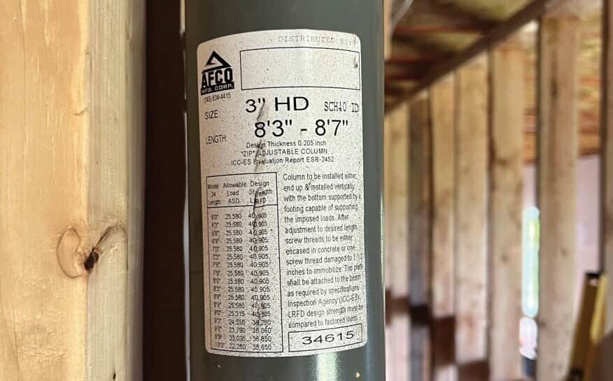
Prevention: First, ensure that the full specifications include the size and type of column and that the rated capacity of the columns is stated on the construction documents. Second, make sure your firm sources the appropriate column called out in the specifications that achieves that rated capacity. Third, verify that the installers are aware of the installation requirements (for example, they know whether the screw-jack assembly needs to be encased in concrete, know which end is designated as “top,” and so forth) and are clear on where each column is to be placed. This is especially important when columns with differing load capacities are specified for the same house.
Out-of-Level Wall Top Plates
Wall top plates that aren’t level often go hand-in-hand with out-of-level foundations. Experienced framers will ensure they are building from a level foundation—and they also will check for level at each framing level. Modern construction practices often rely on precut studs or prefabricated wall panels to increase the speed of production. If these components are not checked as they are installed, an out-of-level floor condition can go unnoticed until an “easy” fix is no longer viable.

Prevention: It’s good practice for builders and subcontractors to check for level at each floor. Also, they should make no assumptions about installing prefabricated components—everything should be measured and verified as the components are installed at each level.
Balloon-Framed Wall Construction
As of the 2021 IRC, the code provides specifications for wood-frame load-bearing stud walls up to 12 feet tall. Any walls that are taller than 12 feet are required to be engineered to resist both gravity and wind loading. A stacked wall is not adequate to resist wind forces against the face of the wall—the studs need to be continuous over the full height of the wall. The balloon-framed construction information should be provided on the construction documents and, depending on conditions, may be designed in a variety of ways. Make sure framers are aware of the design intent—that they know why they are being asked to build in a specific way. We feel that having the framers understand the design is the best way to ensure that the final construction matches the design provided in the construction documents. This also makes sure it happens at the beginning of framing, as retrofits can be especially tricky after the exterior wall sheathing has been applied or windows and doors have been installed.

Prevention: We always recommend that builders go through the plans with the framers to review and understand how balloon-framed walls are intended to be framed. If there are any questions about the design, the builder should reach out to the building designer for clarification. This is especially important for tall walls with multiple openings, like a great-room window wall where additional king studs are required.
Supplier Substitutions
Unapproved supplier substitutions have become increasingly prevalent in recent years with the supply-chain issues that have plagued our industry. Builders and their suppliers will often make substitutions on the fly to maintain schedules. All material substitutions should be verified with the design professionals—but the reality is that doesn’t always happen. We are often questioned about substitutions well in advance of construction—but there are still many cases where a material substitution is caught only after it has been installed. This can lead to costly structural repairs if the material or product used as a substitute for what was specified was not adequate.
Prevention: An experienced builder knows that any structural material substitutions need to be verified by the design professionals. It is not the supplier’s responsibility to select an “equivalent” material or product—it is up to the professional who prepared the construction plans to make that determination. And while builders may have good reasons for pushing ahead to get the job done, they may not always be aware of the many factors that the engineers consider when integrating materials into a structural design. It’s well worth a little extra time to ask the designer for clarification when you need to make a substitution.
Shear Wall/Braced Wall Construction
Bracing walls is an especially important aspect of wood frame construction that can be easily overlooked. The shear-wall construction is especially important in regions with high wind speeds and/or high seismic activity, but it should not be overlooked in areas with low wind speeds, either. It is especially important to understand given the shift in code requirements over the past 10 to 15 years. When designing for even low-wind-speed regions, engineers are required to detail and specify proper load paths for both lateral and uplift loads.
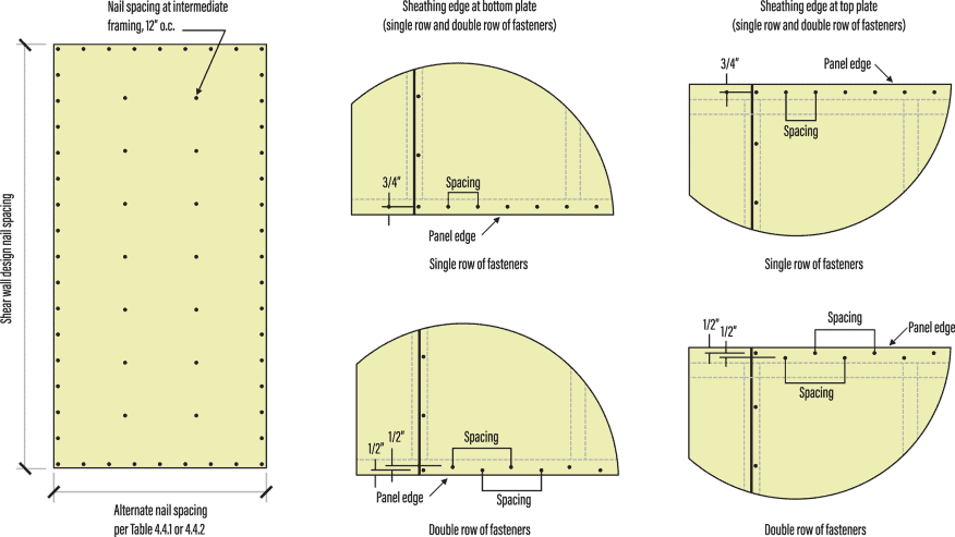
Prevention: Knowledge is power. We recommend builders review the plans prior to construction so they are aware of these requirements and ensure that the framers understand and follow all notes, details, and specifications. Shear wall engineering and detailing is an easily misunderstood aspect of construction. When in doubt, ask for more clarification from the engineer prior to moving forward when possible. Based on feedback from builders, we’ve found that providing graphic details that depict a condition—in lieu of written descriptions on the structural plans or within the structural notes—is often the best way to help field personnel understand the design.
Incorrect Roof Truss Bracing
Roof truss bracing is commonly installed incorrectly on the projects that we inspect or review, even when it’s clearly detailed on the structural plans and truss shop drawings. This is largely due to the complexity of the bracing requirements and the fact that those requirements come from multiple sources. The truss manufacturer is responsible for providing the bracing requirements for individual truss members. This is the most easily recognized portion of the bracing that is shown on the truss shop drawings. However, there is another level of bracing that is required, known as the “Permanent Restraint or Roof Truss System Bracing.” This bracing is specified in the BCSI (Building Component Safety Information) manual under Chapter B3 and may also be provided on the construction documents. The silver lining here is that most truss bracing is easily modified or retrofitted. In most cases, truss bracing is easily added, but it’s easier if it can be added during the construction phase.

Prevention: A builder’s construction team working with roof trusses should have access to and familiarity with Chapter B3 of the BCSI. In those 15 or so pages, diagrams and graphics are provided to help present the material. It is also important that builders understand that they are responsible for installing the bracing correctly, even if the building officials don’t see it or properly enforce it. Our firm has been involved in multiple situations where improperly installed and/or missing truss bracing wasn’t caught until a homeowner’s third-party inspector went through the house. It is much easier to complete the truss bracing correctly during construction than it is to disclose to a homeowner (or whole community of homeowners) that a critical structural component was never installed.
Ultimately, reviewing the plans, details, and other construction documents with the various trades prior to starting a project and providing adequate oversight will pay dividends in avoiding costly errors and time-consuming delays. If something in the construction documents is unclear, seek out the design professionals. It is in everyone’s best interest to clarify design intent before starting or continuing with any project. Also, builders can empower their trades to think of the project as a team effort and point out issues and deficiencies as soon as they are identified. This investment in coordination will help reduce mistakes before construction progresses too far, avoiding repairs that become much more costly down the line. The number of requests for added clarification (or RFIs) that our firm receives is far lower than the number of (often costly) structural repairs we prepare for common construction errors. Customer service is an integral part of our firm’s operations, so we actively encourage questions and feedback from our customers to ensure they are receiving constructable and cost-efficient designs.■