Our article in this month’s issue of Structure Magazine examines how different lateral restraint system classifications can impact the bottom line. Kudos to the author – M+K employee Timothy R. Donahue, P.E.. Great job Tim!
Seismic Response Factor in Cold-Formed Steel Flat Strapped Lateral Systems
Two seismic designs are compared in a hypothetical 10-story building.
Generally speaking, for a given structure, the higher the seismic response factor (R) value is, the more ductile the structure is and the lower the total seismic load acting on the building. With this concept in mind, one might conclude that reducing the seismic load acting on a building by selecting a more ductile seismic force restraint system (SFRS) with a higher R value would ultimately lower the material cost; however, when evaluating the overall cost implications for what it takes to achieve the increased ductility, the cost savings may not always be realized. This is primarily due to the requirements of overstrength factors in the design and detailing of the straps and other protected components of the SFRS with an R greater than 3.
For cold-formed steel framed buildings utilizing flat strap bracing in Seismic Design Categories (SDC) B or C, the structural engineer can design for either an R of 3 by classifying the SFRS as “Steel Systems Not Specifically Detailed For Seismic Resistance”, or for an R of 4 by classifying the SFRS as “Light-frame (cold-formed steel) wall systems using flat strap bracing” (per AISI Section A1.2.3 and Table 12.2-1 of ASCE 7-16).
Due to increased ductility, buildings designed with an R of 4 have story forces that are 25% less compared to a building designed using an R of 3. To achieve the higher ductility however, more in depth design of the protected components is required in accordance with AISI-400, Section E3.2. These protected components include collectors, connections of strap bracing, chord studs, vertical boundary elements, and floor to floor connections of the boundary elements (see figure 1). This is to ensure that the energy dissipating elements (the straps) yield while the boundary members and connections remain elastic.

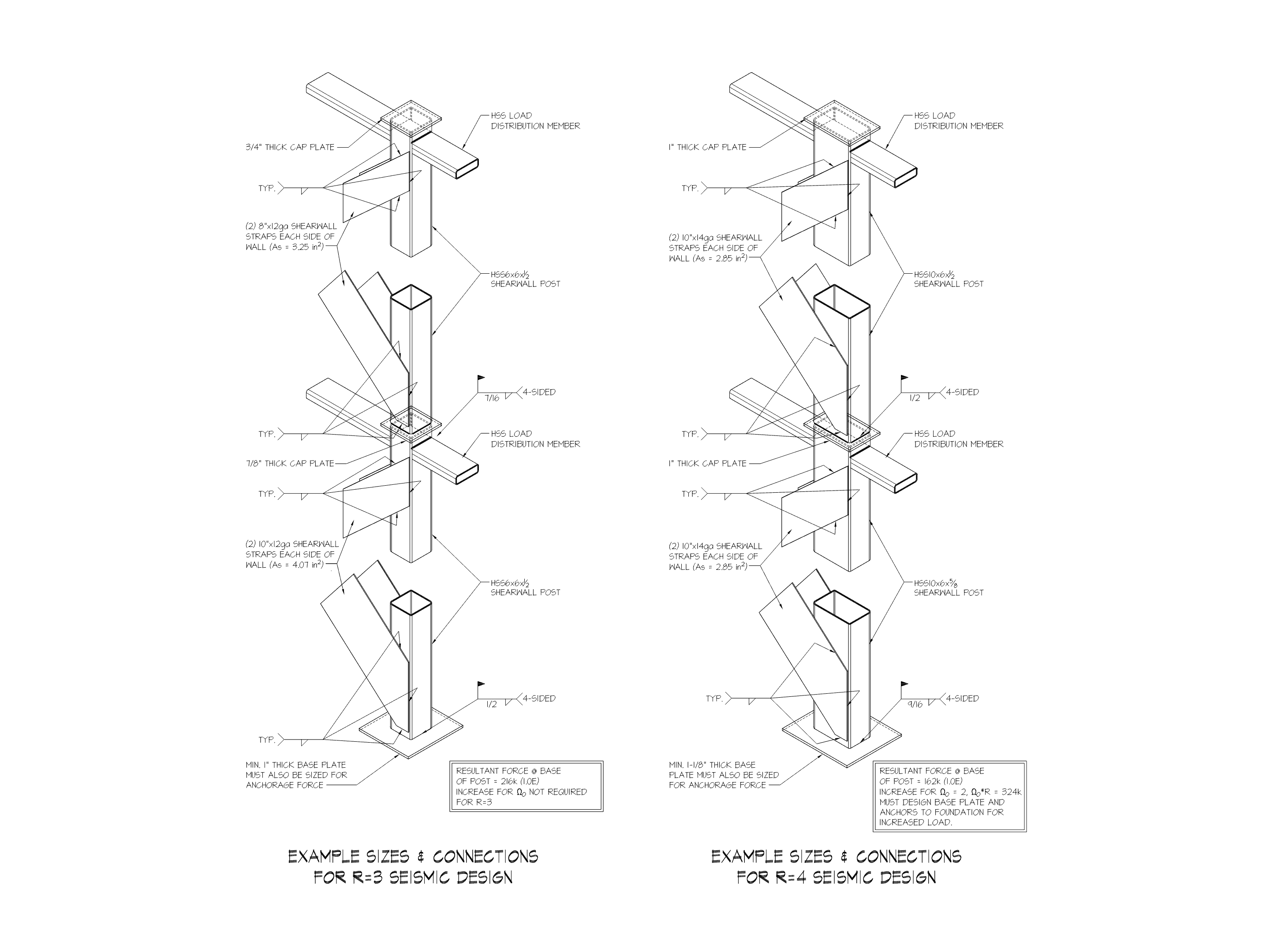
To better understand the potential cost implications of the two different designs, let’s look at a typical end post connection of a hypothetical ten story building, in SDC B, that uses a light gauge strapped wall bracing SFRS. Figure 1 shows the connection design for the R=3 case, while Figure 2 shows the connection design for R=4.
As expected, the strap sizes are slightly smaller (or lighter) for the design utilizing an R of 4, as the lower base shear values result in lower strap forces. However, the end post sizes are larger for the R=4 design in order to provide enough weld length for the end post tensile and shear forces. While there are other potential solutions to resolving the increased connection forces beyond increasing the post size, such as adding angles or gussets, each solution ultimately adds cost to the assembly which offsets or negates the savings found in the straps.
Another element of the SFRS that is impacted by the overstrength requirements is the anchorage of the assembly to the concrete foundation. For the aforementioned building, the embed plate with welded studs used to transfer the loads into the foundation would need to accommodate 324 kips of total load for the R=4 design once overstrength is applied but would only need to account for 215 kips in total for the R=3 design. The larger forces, once the overstrength factor is applied, for the R=4 condition results in a more expensive base connection.
In this specific test case, the lower base shear obtained by using the higher R factor did not correlate to a more economical structure. The more ductile design (with R = 4) is in fact quite a bit more costly than the simplified design (with R = 3) despite having to resist lower seismic loads. While this result will not always be the case and there often is potential to economize a building’s lateral design by taking advantage of the reduced story shears resulting from an R of 4, the cost impact of overstrength requirements needs to be considered when selecting the SFRS.■

